Guten Tag,
Let us create a simple description of the process from the original one that the BA has before starting.
How? Well, you open Intalio Designer. Create a new Project, by selecting File->New->Intalio|BPMS Business Process Project; write down the name of the new project and configure the environment (by default, just say OK on this part). Then, you have an empty project with a single sub-directory named “build” ( 😯 “DO NOT TOUCH!!!” 😯 ).
In Intalio Designer you identify several zones of the screen: the menus at the top, the Process Explorer on the left, the drawing or working area (empty) at the center and up to the right margin; at the bottom you’ll also find two small windows with detailed descriptions, and at the bottom margin you’ll see the tabs chooser (on the left) and the status of the compiler/ deployer (on the right).

In each project, you can create as many process descriptions as you want. The idea is to create one diagram per process description, so let us do it: Right-click on the name of the project, and a menu will appear. Choose New->Business Process Diagram. Then, write down the name of the BP (it can be the same than for the project, no problem).
A new process diagram is created, opened in the drawing area, and a couple of default elements have been pre-built: a default pool, and a default task.
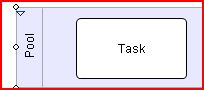 What is a pool? very briefly, it is the representation of the space of action of a given role/actor; it is used as a graphical container of all the tasks that are performed by such a role.
And, what is a task? well, a task is an action or activity performed by a role. It must be put inside a container (pool) in order to be assigned to that role. Tasks are what is listed in our original process description.
Making the system more comfortable for Business Process Modelers
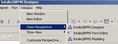
The default perspective in Intalio is the Intalio|BPMS Designer perspective, , that contains the detail needed by the IT specialists. In order to change it, please choose the view menu (top right corner, or go to Window->Open Perspective->Intalio|BPMS Modeling or Window->Open Perspective->Other->Intalio|BPMS Modeling ). This view will allow the BA to use the whole space for the process diagram.
Choose the Palette tab (behind the Project Explorer). The palette offers you the whole set of BPMN symbols you need in order to create your graphical process description. If you want to put a task symbol in the pool, then you click on the Task symbol, and then you click on the drawing (do NOT drag it, please). That’s it.
You must set a name. You may either double-click inside the task, or do the modification using the Properties tab (Click on Properties, then at each task in the drawing. You can edit the content of Properties->Process Execution->Label)
(If you want a full description of this step, please go and visit the Intalio Tutorials and Screencasts in order to understand how to introduce the symbols. My goal with this blog is not to replace the documentation that is already there.)
Specifying the causal relationships: what comes after what
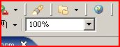
Continue introducing as many tasks as you have in the list of the original process description. Put the next task always to the right of the preceding one. Try not to be too generous, since screen real-state is scarce. You can also zoom out from the menu bar (the only option with the % sign in it 🙂 ).
You will get a long “chorizo” of tasks. They’re not a network of consecutive tasks yet. This is why a red error symbol appears at the left margin of the pool when you save the file (CTRL+S).


As you see, by default, the tasks are done in linear-sequence. However, most interesting processes are made up of a non-linear sequence patterns (parallel, one task-or-the-other, a-minimum-of-iterations-of-a-task, a-minimum-of-instances-of-tasks, etc.). For the moment, we will not address these issues.
Once you finish entering the tasks in sequence, we have a first version of the process. Isn’t it difficult to change the control flow later? NO!! 🙂 That’s the good thing of BPMN and Intalio. It is actually pretty easy, as we will see in a future entry.
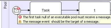 Now you’re notified of an error when you save the project. Mmmmmhh… if you put the mouse over the error symbol on the first task of your process, you should read “The first task of an executable pool must receive a message” … :-?? It is not that terrible, but we have to go back to the original process description:
- what is the event that can trigger this process? what makes the organization to launch a process like this?
- Is it a request/claim made by the person herself or by indirect means?
- If it is the person: can she do it by mailing a letter? can it be done by phone? by fax? by e-mail? via a form in a website?
- If it is done indirectly: what is the kind of system and of information that is received? what are the rules that enable the detection of a certain condition?
 Very often, we can represent the launch of a process as an event, one that arrives or that is detected. This is represented by a Starting Event. The Intalio Palette proposes three events: Empty, Message, and Rule. Please select the Message Start. Put it as the first element in your process timeline.
Specifying the causal relationships: connecting to an external trigger
As the message must come from somewhere external to the orchestrator, you should draw another pool. Select the Pool from the Palette, and then draw it in the working area. It should be a non-executable pool, as explained here, since it is an external actor or system the one who initiates the process. It is not an element under the control of the orchestrator. Click once with the right-button of the mouse, and choose the last option of the list, Set pool non executable. As a result, the left margin of the pool becomes dark.
Put a task in this new, external pool: choose the Task from the Palette, and then draw it in the working area. This time no error is notified, since the non executable pools do not require an external starter.

Save the project. Both the error symbol and the error messages have disappeared.
BPMN is very zealous about well-formedness: please close every opening element, and start and end every process explicitly. I know! I know! Intalio is not telling you anything, but it will surely if you don’t correct the situation early. Pls listen to me: avoid the problems and save time. In this case, the orchestrator should include an explicit termination, and End Event. Please select the Empty End from the Palette, and then draw it in the working area, at the right of the chain of tasks. Insert a Flow Connector from the preceding task. We’re done.
The first iteration of our BP-model is complete. It is not possible to generate an executable description from this first model. We will see why very soon.
Vaarwel !!
